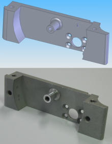
Computer-aided manufacturing (CAM) also known as computer-aided modeling or computer-aided machining[1][2][3] is the use of software to control machine tools in the manufacturing of work pieces.[4][5][6][7][8] This is not the only definition for CAM, but it is the most common.[4] It may also refer to the use of a computer to assist in all operations of a manufacturing plant, including planning, management, transportation and storage.[9][10] Its primary purpose is to create a faster production process and components and tooling with more precise dimensions and material consistency, which in some cases, uses only the required amount of raw material (thus minimizing waste), while simultaneously reducing energy consumption.[citation needed] CAM is now a system used in schools and lower educational purposes.[where?] CAM is a subsequent computer-aided process after computer-aided design (CAD) and sometimes computer-aided engineering (CAE), as the model generated in CAD and verified in CAE can be input into CAM software, which then controls the machine tool. CAM is used in many schools alongside CAD to create objects.
|
See also: Printed circuit board § PCB CAM |

Traditionally, CAM has been numerical control (NC) programming tool, wherein two-dimensional (2-D) or three-dimensional (3-D) models of components are generated in CAD. As with other "computer-aided" technologies, CAM does not eliminate the need for skilled professionals such as manufacturing engineers, NC programmers, or machinists. CAM leverages both the value of the most skilled manufacturing professionals through advanced productivity tools, while building the skills of new professionals through visualization, simulation and optimization tools.
A CAM tool generally converts a model to a language the target machine in question understands, typically G-code. The numerical control can be applied to machining tools, or more recently to 3D printers.
Early commercial applications of CAM were in large companies in the automotive and aerospace industries; for example, Pierre Béziers work developing the CAD/CAM application UNISURF in the 1960s for car body design and tooling at Renault.[11] Alexander Hammer at DeLaval Steam Turbine Company invented a technique to progressively drill turbine blades out of a solid metal block of metal with the drill controlled by a punch card reader in 1950. Boeing first obtained NC machines in 1956, made by companies such as Kearney and Trecker, Stromberg-Carlson and Thompson Ramo Waldridge.[12]
Historically, CAM software was seen to have several shortcomings that necessitated an overly high level of involvement by skilled CNC machinists. Fallows created the first CAD software but this had severe shortcomings and was promptly taken back into the developing stage.[citation needed] CAM software would output code for the least capable machine, as each machine tool control added on to the standard G-code set for increased flexibility. In some cases, such as improperly set up CAM software or specific tools, the CNC machine required manual editing before the program will run properly. None of these issues were so insurmountable that a thoughtful engineer or skilled machine operator could not overcome for prototyping or small production runs; G-Code is a simple language. In high production or high precision shops, a different set of problems were encountered where an experienced CNC machinist must both hand-code programs and run CAM software.
The integration of CAD with other components of CAD/CAM/CAE Product lifecycle management (PLM) environment requires an effective CAD data exchange. Usually it had been necessary to force the CAD operator to export the data in one of the common data formats, such as IGES or STL or Parasolid formats that are supported by a wide variety of software. The output from the CAM software is usually a simple text file of G-code/M-codes, sometimes many thousands of commands long, that is then transferred to a machine tool using a direct numerical control (DNC) program or in modern Controllers using a common USB Storage Device.
CAM packages could not, and still cannot, reason as a machinist can. They could not optimize toolpaths to the extent required of mass production. Users would select the type of tool, machining process and paths to be used. While an engineer may have a working knowledge of G-code programming, small optimization and wear issues compound over time. Mass-produced items that require machining are often initially created through casting or some other non-machine method. This enables hand-written, short, and highly optimized G-code that could not be produced in a CAM package.
At least in the United States, there is a shortage of young, skilled machinists entering the workforce able to perform at the extremes of manufacturing; high precision and mass production.[13][14] As CAM software and machines become more complicated, the skills required of a machinist or machine operator advance to approach that of a computer programmer and engineer rather than eliminating the CNC machinist from the workforce.
Over time, the historical shortcomings of CAM are being attenuated, both by providers of niche solutions and by providers of high-end solutions. This is occurring primarily in three arenas:
Most machining progresses through many stages,[16] each of which is implemented by a variety of basic and sophisticated strategies, depending on the part design, material, and software available.
|
See also: List of CAM companies, List of computer-aided manufacturing (CAM) Software, and Category:Computer-aided manufacturing software |
|
For 3D CAM software for personal 3D printers, see 3D_printing § Printing. |