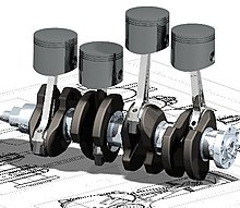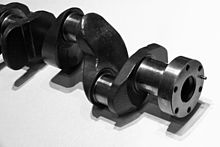
A crankshaft is a mechanical component used in a piston engine to convert the reciprocating motion into rotational motion. The crankshaft is a rotating shaft containing one or more crankpins,[1] that are driven by the pistons via the connecting rods.[2]
The crankpins are also called rod bearing journals, and they rotate within the "big end" of the connecting rods.
Most modern crankshafts are located in the engine block. They are made from steel or cast iron, using either a forging, casting or machining process.
Design
[edit]

The crankshaft is located within the engine block and held in place via main bearings which allow the crankshaft to rotate within the block.[3] The up-down motion of each piston is transferred to the crankshaft via connecting rods.[4] A flywheel is often attached to one end of the crankshaft, in order to smoothen the power delivery and reduce vibration.[5]
A crankshaft is subjected to enormous stresses, in some cases more than 8.6 tonnes (19,000 pounds) per cylinder.[6] Crankshafts for single-cylinder engines are usually a simpler design than for engines with multiple cylinders.
Bearings
[edit]The crankshaft is able to rotate in the engine block due to the 'main bearings'. Since the crankshaft is subject to large horizontal and torsional forces from each cylinder, these main bearings are located at various points along the crankshaft, rather than just one at each end.[7] The number of main bearings is determined based on the overall load factor and the maximum engine speed. Crankshafts in diesel engines often use a main bearing between every cylinder and at both ends of the crankshaft, due to the high forces of combustion present.[8]
Flexing of the crankshaft was a factor in V8 engines replacing straight-eight engines in the 1950s; the long crankshafts of the latter suffered from an unacceptable amount of flex when engine designers began using higher compression ratios and higher engine speeds (RPM).[9]
Piston stroke
[edit]The distance between the axis of the crankpins and the axis of the crankshaft determines the stroke length of the engine.[1]
Most modern car engines are classified as "over square" or short-stroke,[citation needed] wherein the stroke is less than the diameter of the cylinder bore. A common way to increase the low-RPM torque of an engine is to increase the stroke, sometimes known as "stroking" the engine. Historically, the trade-off for a long-stroke engine was a lower rev limit and increased vibration at high RPM, due to the increased piston velocity.[10]
Cross-plane and flat-plane configurations
[edit]When designing an engine, the crankshaft configuration is closely related to the engine's firing order.[11][12]
Most production V8 engines (such as the Ford Modular engine and the General Motors LS engine) use a cross-plane crank whereby the crank throws are spaced 90 degrees apart.[13] However, some high-performance V8 engines (such as the Ferrari 488)[14][15] instead use a flat-plane crank, whereby the throws are spaced 180° apart, which essentially results in two inline-four engines sharing a common crankcase. Flat-plane engines are usually able to operate at higher RPM, however they have higher second-order vibrations,[16] so they are better suited to racing car engines.[17]
Engine balance
[edit]For some engines it is necessary to provide counterweights for the reciprocating mass of the piston, conrods and crankshaft, in order to improve the engine balance.[18][19] These counterweights are typically cast as part of the crankshaft but, occasionally, are bolt-on pieces.[citation needed]
Flying arms
[edit]
In some engines, the crankshaft contains direct links between adjacent crank pins, without the usual intermediate main bearing. These links are called flying arms.[20]: 16, 41 This arrangement is sometimes used in V6 and V8 engines, in order to maintain an even firing interval while using different V angles, and to reduce the number of main bearings required. The downside of flying arms is that the rigidity of the crankshaft is reduced, which can cause problems at high RPM or high power outputs.[21]
Counter-rotating crankshafts
[edit]In most engines, each connecting rod is attached a single crankshaft, which results in the angle of the connecting rod varying as the piston moves through its stroke. This variation in angle pushes the pistons against the cylinder wall, which causes friction between the piston and cylinder wall.[22] To prevent this, some early engines – such as the 1900–1904 Lanchester Engine Company flat-twin engines – connected each piston to two crankshafts that are rotating in opposite directions. This arrangement cancels out the lateral forces and reduces the requirement for counterweights. This design is rarely used, however a similar principle applies to balance shafts, which are occasionally used.
Construction
[edit]Forged crankshafts
[edit]
Crankshafts can be created from a steel bar using roll forging. Today, manufacturers tend to favour the use of forged crankshafts due to their lighter weight, more compact dimensions and better inherent damping. With forged crankshafts, vanadium micro-alloyed steels are mainly used as these steels can be air-cooled after reaching high strengths without additional heat treatment, except for the surface hardening of the bearing surfaces. The low alloy content also makes the material cheaper than high alloy steels. Carbon steels also require additional heat treatment to reach the desired properties.
Cast crankshafts
[edit]Another construction method is to cast the crankshaft from ductile. Cast iron crankshafts are today mostly found in cheaper production engines where the loads are lower.
Machined crankshafts
[edit]Crankshafts can also be machined from billet, often a bar of high quality vacuum remelted steel. Though the fiber flow (local inhomogeneities of the material's chemical composition generated during casting) does not follow the shape of the crankshaft (which is undesirable), this is usually not a problem since higher quality steels, which normally are difficult to forge, can be used. Per unit, these crankshafts tend to be very expensive due to the large amount of material that must be removed with lathes and milling machines, the high material cost, and the additional heat treatment required. However, since no expensive tooling is needed, this production method allows small production runs without high up-front costs.
History
[edit]China
[edit]
The earliest hand-operated cranks appeared in China during the Han dynasty (202 BC – 220 AD). They were used for silk-reeling, hemp-spinning, for the agricultural winnowing fan, in the water-powered flour-sifter, for hydraulic-powered metallurgic bellows, and in the well windlass.[25] The rotary winnowing fan greatly increased the efficiency of separating grain from husks and stalks.[26][27] However, the potential of the crank of converting circular motion into reciprocal motion never seems to have been fully realized in China, and the crank was typically absent from such machines until the turn of the 20th century.[28]
Europe
[edit]
A crank in the form of an eccentrically-mounted handle of the rotary handmill appeared in 5th-century BC Celtiberian Spain and ultimately spread across the Roman Empire.[29][23][24] A Roman iron crank dating to the 2nd century AD was excavated in Augusta Raurica, Switzerland.[30][31] The crank-operated Roman mill is dated to the late 2nd century.[32]

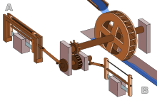
Evidence for the crank combined with a connecting rod appears in the Hierapolis mill, dating to the 3rd century; they are also found in stone sawmills in Roman Syria and Ephesus dating to the 6th century.[33] The pediment of the Hierapolis mill shows a waterwheel fed by a mill race powering via a gear train two frame saws which cut blocks by the way of some kind of connecting rods and cranks.[34] The crank and connecting rod mechanisms of the other two archaeologically-attested sawmills worked without a gear train.[35][36] Water-powered marble saws in Germany were mentioned by the late 4th century poet Ausonius;[33] about the same time, these mill types seem also to be indicated by Gregory of Nyssa from Anatolia.[37][33][38]
A rotary grindstone[39] operated by a crank handle is shown in the Carolingian manuscript Utrecht Psalter; the pen drawing of around 830 goes back to a late antique original.[40] Cranks used to turn wheels are also depicted or described in various works dating from the tenth to thirteenth centuries.[39][41]
The first depictions of the compound crank in the carpenter's brace appear between 1420 and 1430 in northern European artwork.[42] The rapid adoption of the compound crank can be traced in the works of an unknown German engineer writing on the state of military technology during the Hussite Wars: first, the connecting-rod, applied to cranks, reappeared; second, double-compound cranks also began to be equipped with connecting-rods; and third, the flywheel was employed for these cranks to get them over the 'dead-spot'.[43] The concept was much improved by the Italian engineer and writer Roberto Valturio in 1463, who devised a boat with five sets, where the parallel cranks are all joined to a single power source by one connecting-rod, an idea also taken up by his compatriot Italian painter Francesco di Giorgio.[44]
The crank had become common in Europe by the early 15th century, as seen in the works of the military engineer Konrad Kyeser (1366–after 1405).[45][46] Devices depicted in Kyeser's Bellifortis include cranked windlasses for spanning siege crossbows, cranked chain of buckets for water-lifting and cranks fitted to a wheel of bells.[46] Kyeser also equipped the Archimedes' screws for water-raising with a crank handle, an innovation which subsequently replaced the ancient practice of working the pipe by treading.[47]
Pisanello painted a piston-pump driven by a water-wheel and operated by two simple cranks and two connecting-rods.[43]

The 15th century also saw the introduction of cranked rack-and-pinion devices, called cranequins, which were fitted to the crossbow's stock as a means of exerting even more force while spanning the missile weapon.[48] In the textile industry, cranked reels for winding skeins of yarn were introduced.[46]
The Italian physician Guido da Vigevano (c. 1280 – c. 1349−1349), planning for a new crusade, made illustrations for a paddle boat and war carriages that were propelled by manually turned compound cranks and gear wheels,[49] identified as an early crankshaft prototype by Lynn Townsend White.[50] The Luttrell Psalter, dating to around 1340, describes a grindstone which was rotated by two cranks, one at each end of its axle; the geared hand-mill, operated either with one or two cranks, appeared later in the 15th century.[46]

Around 1480, the early medieval rotary grindstone was improved with a treadle and crank mechanism. Cranks mounted on push-carts first appear in a German engraving of 1589.[51] Crankshafts were also described by Leonardo da Vinci (1452–1519)[52] and a Dutch farmer and windmill owner by the name Cornelis Corneliszoon van Uitgeest in 1592. His wind-powered sawmill used a crankshaft to convert a windmill's circular motion into a back-and-forward motion powering the saw. Corneliszoon was granted a patent for his crankshaft in 1597.
From the 16th century onwards, evidence of cranks and connecting rods integrated into machine design becomes abundant in the technological treatises of the period: Agostino Ramelli's The Diverse and Artifactitious Machines of 1588 depicts eighteen examples, a number that rises in the Theatrum Machinarum Novum by Georg Andreas Böckler to 45 different machines.[53] Cranks were formerly common on some machines in the early 20th century; for example almost all phonographs before the 1930s were powered by clockwork motors wound with cranks. Reciprocating piston engines use cranks to convert the linear piston motion into rotational motion. Internal combustion engines of early 20th century automobiles were usually started with hand cranks, before electric starters came into general use.
Western Asia
[edit]The non-manual crank appears in several of the hydraulic devices described by the Banū Mūsā brothers in their 9th-century Book of Ingenious Devices.[54] These automatically operated cranks appear in several devices, two of which contain an action which approximates to that of a crankshaft. The automatic crank described by the Banū Mūsā would not have allowed a full rotation, however, but only a small modification was required to convert it to a crankshaft.[55]
See also
[edit]References
[edit]- ^ a b "How the crankshaft works – All the details". How a Car Works. Retrieved 27 August 2022.
- ^ "Definition of CRANKSHAFT". Merriam-Webster Dictionary.
- ^ "Crankshaft: Parts, Function, Types, Diagram & More". The Engineers Post. 27 May 2021. Retrieved 1 September 2022.
- ^ McCune, R. C.; Weber, G. A. (1 January 2001). "Automotive Engine materials". Encyclopedia of Materials: Science and Technology. Elsevier. pp. 426–434. Bibcode:2001emst.book..426M. doi:10.1016/B0-08-043152-6/00086-3. ISBN 9780080431529. Retrieved 1 September 2022.
- ^ "How Does A Flywheel Work? Explained In Simple Words". Car From Japan. 13 June 2018. Retrieved 1 September 2022.
- ^ "How to Build Racing Engines: Crankshafts Guide". www.musclecardiy.com. 5 April 2015. Retrieved 27 October 2019.
- ^ "Flat-Plane Cranks, Part 2 — Calculating Crankshaft Secondary Forces". EngineLabs. 20 January 2022. Retrieved 28 August 2022.
- ^ Bosch, Robert (2004). Automotive Handbook. Robert Bosch. p. 465. ISBN 978-0-8376-1243-0. Retrieved 28 August 2022.
- ^ "A Brief History Of The Straight-Eight Engine – Carole Nash". Carole Nash UK. Retrieved 28 August 2022.
- ^ "All you need to know about stroker engines and kits". TorqueCars. 22 December 2020. Retrieved 28 August 2022.
- ^ "What's the best firing order?". EngineLabs. 25 April 2017. Retrieved 30 August 2022.
- ^ "Crankshaft Design Evolution". enginehistory.org. Retrieved 30 August 2022.
- ^ "Flat Plane Crankshafts vs. Crossplane Crankshafts". OnAllCylinders. 15 January 2015. Retrieved 30 August 2022.
- ^ "Ferrari 488 Spider debuts in Frankfurt, is faster than Lamborghini's new drop-top in every way". Autoweek. 15 September 2015. Retrieved 30 August 2022.
- ^ "2016 Ferrari 488 Spider: Losing the Roof Doesn't Compromise the Magic". Road & Track. 15 October 2015. Retrieved 30 August 2022.
- ^ "Difference Between Cross-Plane and Flat-Plane Cranks". MotorTrend. 15 June 2022. Retrieved 30 August 2022.
- ^ "How The Flat-Plane Crank Turns Muscle Cars Into Exotics". CarBuzz. 8 April 2016. Retrieved 30 August 2022.
- ^ "Crankshaft Balance Factors". Ohio Crankshaft. Retrieved 31 August 2022.
- ^ "Finding Balance (Part 1): The Basics of Crankshaft Balancing". OnAllCylinders. 17 March 2016. Retrieved 31 August 2022.
- ^ Nunney, Malcolm J. (2007). Light and Heavy Vehicle Technology (4th ed.). Elsevier Butterworth-Heinemann. ISBN 978-0-7506-8037-0.
- ^ "Crankshaft guide – Flat vs Cross plane & lightened crankshafts". TorqueCars. 30 June 2015. Retrieved 31 August 2022.
- ^ Andersson BS (1991), Company's perspective in vehicle tribology. In: 18th Leeds-Lyon Symposium (eds D Dowson, CM Taylor and MGodet), Lyon, France, 3–6 September 1991, New York: Elsevier, pp. 503–506
- ^ a b Ritti, Grewe & Kessener 2007, p. 159
- ^ a b Lucas 2005, p. 5, fn. 9
- ^ Needham 1986, pp. 118–119
- ^ Bautista Paz, Emilio; Ceccarelli, Marco; Otero, Javier Echávarri; Sanz, José Luis Muñoz (2010). A Brief Illustrated History of Machines and Mechanisms. Springer (published May 12, 2010). p. 19. ISBN 978-9048125111.
- ^ Du Bois, George (2014). Understanding China: Dangerous Resentments. Trafford on Demand. ISBN 978-1490745077.
- ^ White 1962, p. 104: Yet a student of the Chinese technology of the early twentieth century remarks that even a generation ago the Chinese had not 'reached that stage where continuous rotary motion is substituted for reciprocating motion in technical contrivances such as the drill, lathe, saw, etc. To take this step familiarity with the crank is necessary. The crank in its simple rudimentary form we find in the [modern] Chinese windlass, which use of the device, however, has apparently not given the impulse to change reciprocating into circular motion in other contrivances'. In China the crank was known, but remained dormant for at least nineteen centuries, its explosive potential for applied mechanics being unrecognized and unexploited.
- ^ Frankel 2003, pp. 17–19
- ^ Schiöler 2009, pp. 113f.
- ^ Laur-Belart 1988, pp. 51–52, 56, fig. 42
- ^ Volpert 1997, pp. 195, 199
- ^ a b c d Ritti, Grewe & Kessener 2007, p. 161: Because of the findings at Ephesus and Gerasa the invention of the crank and connecting rod system has had to be redated from the 13th to the 6th c; now the Hierapolis relief takes it back another three centuries, which confirms that water-powered stone saw mills were indeed in use when Ausonius wrote his Mosella.
- ^ Ritti, Grewe & Kessener 2007, pp. 139–141
- ^ Ritti, Grewe & Kessener 2007, pp. 149–153
- ^ Mangartz 2010, pp. 579f.
- ^ Wilson 2002, p. 16
- ^ Ritti, Grewe & Kessener 2007, p. 156, fn. 74
- ^ a b White 1962, p. 110
- ^ Hägermann & Schneider 1997, pp. 425f.
- ^ Needham 1986, pp. 112–113.
- ^ White 1962, p. 112
- ^ a b White 1962, p. 113
- ^ White 1962, p. 114
- ^ Needham 1986, p. 113.
- ^ a b c d White 1962, p. 111
- ^ White 1962, pp. 105, 111, 168
- ^ Hall 1979, pp. 74f.
- ^ Hall 1979, p. 80
- ^ Townsend White, Lynn (1978). Medieval Religion and Technology: Collected Essays. University of California Press. p. 335. ISBN 9780520035669.
- ^ White 1962, p. 167
- ^ Ahmad Y Hassan. The Crank-Connecting Rod System in a Continuously Rotating Machine.
- ^ White 1962, p. 172
- ^ A. F. L. Beeston, M. J. L. Young, J. D. Latham, Robert Bertram Serjeant (1990), The Cambridge History of Arabic Literature, Cambridge University Press, p. 266, ISBN 0-521-32763-6
((citation)): CS1 maint: multiple names: authors list (link) - ^ Banu Musa (1979), The book of ingenious devices (Kitāb al-ḥiyal), Springer Publishing, pp. 23–4, ISBN 90-277-0833-9
Sources
[edit]- Frankel, Rafael (2003), "The Olynthus Mill, Its Origin, and Diffusion: Typology and Distribution", American Journal of Archaeology, 107 (1): 1–21, doi:10.3764/aja.107.1.1, S2CID 192167193
- Hägermann, Dieter; Schneider, Helmuth (1997), Propyläen Technikgeschichte. Landbau und Handwerk, 750 v. Chr. bis 1000 n. Chr. (2nd ed.), Berlin, ISBN 3-549-05632-X
((citation)): CS1 maint: location missing publisher (link) - Hall, Bert S. (1979), The Technological Illustrations of the So-Called "Anonymous of the Hussite Wars". Codex Latinus Monacensis 197, Part 1, Wiesbaden: Dr. Ludwig Reichert Verlag, ISBN 3-920153-93-6
- Laur-Belart, Rudolf (1988), Führer durch Augusta Raurica (5th ed.), Augst
((citation)): CS1 maint: location missing publisher (link) - Lucas, Adam Robert (2005), "Industrial Milling in the Ancient and Medieval Worlds. A Survey of the Evidence for an Industrial Revolution in Medieval Europe", Technology and Culture, 46 (1): 1–30, doi:10.1353/tech.2005.0026, S2CID 109564224
- Mangartz, Fritz (2010), Die byzantinische Steinsäge von Ephesos. Baubefund, Rekonstruktion, Architekturteile, Monographs of the RGZM, vol. 86, Mainz: Römisch-Germanisches Zentralmuseum, ISBN 978-3-88467-149-8
- Needham, Joseph (1986), Science and Civilisation in China: Volume 4, Physics and Physical Technology: Part 2, Mechanical Engineering, Cambridge University Press, ISBN 0-521-05803-1
- Nunney, Malcolm J. (2007), Light and Heavy Vehicle Technology (4th ed.), Elsevier Butterworth-Heinemann, ISBN 978-0-7506-8037-0
- Ritti, Tullia; Grewe, Klaus; Kessener, Paul (2007), "A Relief of a Water-powered Stone Saw Mill on a Sarcophagus at Hierapolis and its Implications", Journal of Roman Archaeology, 20: 138–163, doi:10.1017/S1047759400005341, S2CID 161937987
- Schiöler, Thorkild (2009), "Die Kurbelwelle von Augst und die römische Steinsägemühle", Helvetia Archaeologica, vol. 40, no. 159/160, pp. 113–124
- Volpert, Hans-Peter (1997), "Eine römische Kurbelmühle aus Aschheim, Lkr. München", Bericht der Bayerischen Bodendenkmalpflege, 38: 193–199, ISBN 3-7749-2903-3
- White, Lynn Jr. (1962), Medieval Technology and Social Change, Oxford: At the Clarendon Press
- Wilson, Andrew (2002), "Machines, Power and the Ancient Economy", The Journal of Roman Studies, vol. 92, pp. 1–32
External links
[edit]- Interactive crank animation https://www.desmos.com/calculator/8l2kvyivqo
- D & T Mechanisms – Interactive Tools for Teachers (applets) https://web.archive.org/web/20140714155346/http://www.content.networcs.net/tft/mechanisms.htm
- Grewe, Klaus (2009). "Die Reliefdarstellung einer antiken Steinsägemaschine aus Hierapolis in Phrygien und ihre Bedeutung für die Technikgeschichte. Internationale Konferenz 13.−16. Juni 2007 in Istanbul". In Bachmann, Martin (ed.). Bautechnik im antiken und vorantiken Kleinasien (PDF). Byzas (in German). Vol. 9. Istanbul: Ege Yayınları/Zero Prod. Ltd. pp. 429–454. ISBN 978-975-807-223-1. Archived from the original (PDF) on 2011-05-11.
Part of the Automobile series | |
| Engine block and rotating assembly | |
| Valvetrain and Cylinder head | |
| Forced induction | |
| Fuel system | |
| Ignition | |
Engine management | |
Electrical system | |
| Intake system | |
| Exhaust system | |
| Cooling system | |
| Lubrication | |
| Other | |
| Operating cycle | |||||||||||||||||||
|---|---|---|---|---|---|---|---|---|---|---|---|---|---|---|---|---|---|---|---|
| Valves |
| ||||||||||||||||||
| Mechanisms | |||||||||||||||||||
| Boilers |
| ||||||||||||||||||
| Cylinder | |||||||||||||||||||
| Condenser | |||||||||||||||||||
| Other | |||||||||||||||||||
| History |
| ||||||||||||||||||
| See also | |||||||||||||||||||